avg_angle = np.mean(angles) looks like noise filtering. It isn’t. It is a mechanical decision: a human finger has three joints you can move separately, and this robot finger has one string. Not smoothing — compression # “Averaging” in a sensor pipeline usually means averaging over time to reduce noise. Nothing here keeps history between frames. The mean is taken across space — over the three joints of one finger in a single frame — to solve a problem called underactuation.
The 3-to-1 problem # Human finger Robot finger Joints 3 (MCP, PIP, DIP) 3 hinges (*_mcp, *_pip, *_dip) Independent actuators many muscles; joints move semi-independently 1 flexor tendon, 1 motor Degrees of freedom you can command ~3 1 A system with fewer actuators than joints is underactuated. A single tendon threads all three joints of each robot finger, so the only command is “pull this string with force F” — and the joints share that pull according to routing geometry and dynamics.
One string, six via-points, three joints. Pull it and all three knuckles move together. So the vision layer must compress three human measurements into one robot command.
A raw CAD export gives you bodies, joints, meshes and sites — and a hand that does nothing. Four edits and one extra file turn it into a tendon-driven twin. One of those edits, it turns out, does nothing at all — which is worth understanding too. Which edits survive a re-export # flowchart TB subgraph generated["robot.xml — regenerated by onshape-to-robot"] D["① joint defaults
manual — re-apply"] T["② tendons + ③ contacts
auto-injected from tendons.xml"] B["bodies · joints · sites · meshes
generated"] A["④ actuators
manual — re-apply"] end S["⑤ scene.xml
floor · lights · skybox
never regenerated"] -->|"include robot.xml"| generated # Edit Lives in Survives re-export? ① Joint friction / armature / damping defaults robot.xml <default> ✘ re-apply ② Flexor + extensor spatial tendons tendons.xml → injected ✔ ③ Contact exclusions tendons.xml → injected ✔ ④ Five tendon motors robot.xml <actuator> ✘ re-apply ⑤ Environment scene.xml ✔ separate file tendons.xml is kept byte-identical to the <tendon> and <contact> region of robot.xml. Tune a tendon in robot.xml without copying it back and the next export silently reverts it.
① Joint defaults — stability # <default class="ros2-tendon-driven-hand-gazebo-digital-twin"> <joint frictionloss="0.001" armature="0.0001" damping="0.01"/> Attribute Value Role damping 0.01 N·m·s/rad stops a 2 g phalanx reaching absurd speed when 50 N yanks it armature 0.0001 kg·m² rotor-like inertia on each joint’s diagonal — conditions the solver for very light bodies frictionloss 0.001 N·m a small dry-friction dead-band so joints settle instead of creeping Phalanges weigh 1.8–5.4 g. Without these, tiny inertias under large tendon forces blow up the integrator — an earlier, larger revision of the model logged Nan, Inf or huge value in QACC at DOF 128. The simulation is unstable.
The system works, and it teaches well. Getting it to drive real servos safely is a sequence of well-scoped upgrades — each one grounded in a limitation measured earlier in this series. Where it stands # Area Today Production target Hand tracking image-normalized landmarks, one global calibration metric world landmarks, per-finger calibration, a temporal filter Command mapping flexion → ±50 N; the twin is a switch flexion → tendon length; proportional curl Physics model force motors, decorative horns, no self-contact position servos on horns, tuned stiffness, contacts for grasping Middleware one topic, default QoS, open on the LAN parameters, explicit QoS, a watchdog, SROS 2 Containers privileged, host namespaces, root, xhost least privilege, non-root, optional headless Code classes copied into three files, no tests one shared package, tests, CI Hardware simulation only a servo driver on the same topic Stage 1 · Correctness Measure the right thing, command the right quantity World landmarks. Image-normalized coordinates bend angles by up to 16° with hand orientation (Part 4). Read multi_hand_world_landmarks instead, then recalibrate.

The simulated hand was never modelled by hand. It is an Onshape assembly — five SG90 servos, fifteen knuckle mates, a palm full of tendon channels — pulled through the Onshape API and written out as MuJoCo XML. Here is the design, and every setting that steers the export. Open the Onshape assembly The design # Your browser cannot play this video. Download video.
Palm and fingers: four three-phalanx fingers and a three-segment thumb, every knuckle a revolute mate with limits. The RGB triads in the views are mate connectors. Tendon channels: one per finger, running down the palm into the base. Servo block: five SG90-class servos, staggered so each horn sits under a tendon exit. The design has a history # Start 2026-09-02 The first version in the history. v1.0.0 — MediaPipe 2026-09-06 The joint-angle-driven hand behind the RViz predecessor project. v1.0.1 → Main 2026-09-08 Point release and the main line the later work branches from. V3 → Mujoco branch 2026-09-16 The current design used by this twin — the version with the servo base block shown above. Onshape version history Mate features 43 part instances, 112 mate features: the 15 dof_* knuckle mates, the servo mates, and many Fastened mates.
Everything in this series in one read: how a $20 webcam ends up driving a 15-DOF CAD model in real time, why every step is deliberately explicit rather than learned, and what broke along the way. You hold your hand up to a laptop camera. On the other half of the screen, a robotic hand — designed in CAD, never manufactured — closes its fingers at the same moment yours do.
There is no glove, no marker, no depth sensor. Just an RGB webcam, two small neural networks, about forty lines of vector geometry, and a middleware stack that thinks it is talking to a real robot.
All of it is open source under AGPL-3.0 and archived with a DOI: 10.5281/zenodo.22658556.
flowchart LR A["📷 Webcam
/dev/video0"] --> B["BlazePalm
palm detector"] B --> C["Landmark regressor
21 × (x, y, z)"] C --> D["Dot-product geometry
15 interior angles"] D --> E["Normalize → flexion
0.0 straight · 1.0 curled"] E --> F["Lerp onto the URDF's
mechanical limits"] F --> G["/joint_states"] G --> H["robot_state_publisher
→ /tf"] H --> I["🖥️ RViz digital twin"] The rule that shaped the build # There is an easier version of this project. Collect a few thousand frames of a hand next to the corresponding CAD poses, train a network to map one to the other, and let gradient descent work out the relationship.
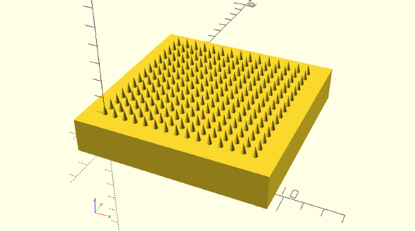
The same 15×15 microneedle array, generated four ways in code. The interesting part isn’t the loops — it’s that three of the four scripts refuse to merge the 225 cones into the baseplate at all, and hand that job to the slicer instead.
Sensor, controller, actuator — all three built into a crystal lattice. What a triple-doped hydroxyapatite scaffold looks like when you read it as a control system.
The manufacturing route behind a published bone scaffold, and an honest comparison against direct ink writing, electrospinning and vat photopolymerisation.